
William Ligon-Bruno/Senior Design Project


Success Criteria Values
This device was successful in both stringing the racquet and stringing the racquet in less time than the conventional drop-weight racquet stringer. With more trials this time could be reduced through minor redesigns. The tension on the racquet was measured throughout the stringing process and was within 5lbs of the set tension.
Conclusion
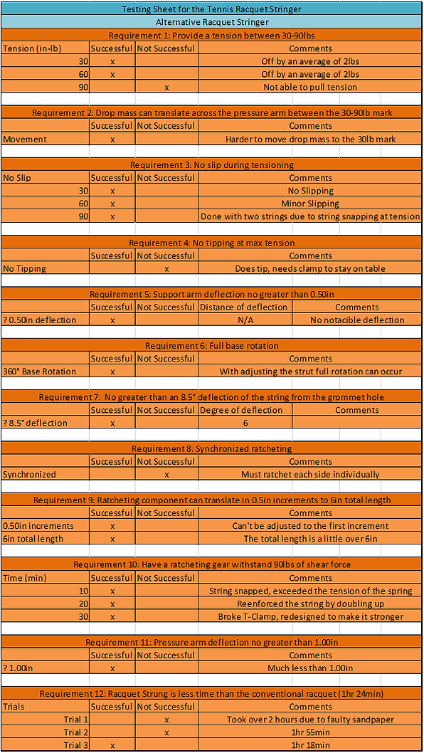
Out of the 12 requirements tested for in the sheet provided in Appendix H, Fig. 1 only 3 were unsuccessful. The first failure was with the 1st requirement which states that the stringer shall provide a tension from 30-90lbs. Although the stringer could provide a tension between 30-60lbs, it could not provide a tension of 90lbs without snapping the string. This is not a terminal failure of the whole device, but merely an overdesign. The tensile strength of the string should have been assessed first and a max tension should have been back-solved from there. The second failure was from requirement 4. This was that the device would not tip. Although it was designed not to tip at the maximum tension of 90lbs, the increase of the drop-mass weight moved the center of gravity enough to cause tipping at 75lbs of tension. Therefore clamps are needed, which again is not a terminal failure of the device. Lastly, the 8th requirement was a failure due to the design not allowing for synchronized ratcheting. The ratcheting was done manually and successively as needed. The ratchets were designed to be symmetrical therefore they ratchet in the same increments. This makes it possible to keep the same tension on both strings while moving each ratchet independently. This is not a critical design failure, but does increase the time to string the racquet. Overall, the design was successful. Many improvements have already been designed for the next model, but for the scope of this project it met the success criteria.
Testing Values
The requirement 1 test was conducted for the 3 tensions stated before. For the 30lb tension the average tension after 5 trials was 32lbs. For the 60lb tension the average tension after 5 trials was 62lbs. For the 90lb tension no trials could be conducted because the string snapped before the tension could be pulled. The stringer surpasses the design limits of the string being used. The mass was almost parallel so an inferred value of 80lbs was the max tension of the string.
The requirement 2 test was a straight forward test involving translating the mass up and down the pressure arms. It was first set at 90lbs and incrementally moved up the shaft. Once it got to 40lbs the difficulty of moving the drop mass significantly increased. Pressure arms had to be squeezed together in order to get the mass to move to the 30lb mark.
The requirement 3 test was needed for all other testing. The tensions 30, 60, and 90lbs were used as a range to ensure no slippage occurred. At 30lbs no slippage occurred or very minimal. At 60lbs the slippage was a little more frequent and tension had to be pulled on the string from the loose end through the ratchet until there was enough rotation for the clamp to activate. A single string was not used for the slippage at 90lbs due to the string snapping. Therefore, 2 strings were used in each ratcheting component and similar to the 60lb test, tension needed to be pulled until clamp activated.
The requirement 4 test was for no tipping. At 50lbs the device starts to lift off the table and at 75lbs it becomes unstable and starts to tip. This relationship can be observed on the graph in Fig. 7 of Appendix I. Clamps were implemented to prevent tipping in the testing that followed.
The requirement 5 test was for the support arm beam deflection. Brackets were installed to keep the support arm in the slot as seen in Appendix I, Fig. 8. During the testing, the support arm does still rotate in the slot, but minimally. At the maximum tension of 90lbs the support arm rotates and stops and the deflection of the support arm is not noticeable. Therefore it is under the specification that it must be under 0.5ins of deflection.
The requirement 6 test was for full swivel arm rotation. With the original design implementation the swivel arm had full rotation however when a racquet was installed the rotation was limited to 320° of rotation due to the shaft of the racquet coming in contact with the support arms and ratcheting system. The struts then had to be placed on the swivel arm as depicted in Appendix I, Fig. 6. When translated to its maximum side position with the racquet mounted, it then has a full 360° rotation with 2.5ins of clearance from the ratcheting system and support arm.
The requirement 7 test was for the deflection of the string from the grommet hole to the ratcheting system. The greatest deflection seen during the racquet stringing process is shown in Fig. 9 of Appendix I. The scaled down picture was measured and the angle was given to be 6.4° which is less than the maximum of 8.5°.
The requirement 8 test was for the synchronized ratcheting. A crank was designed to allow for this although it could not adjust and would have only worked for one setting of the ratchets. Therefore synchronized ratcheting was not possible with this model so ratcheting was done to each side successively with the same increments. If there was slippage of the string one side could be ratcheted while the other did not have to.
The requirement 9 test was the lateral translation of the ratcheting components along the axis of rotation. 5 holes were made, but due to a manufacturing error only 4 holes could be utilized as seen in Appendix I, Fig. 10. This did not affect the ability of the ratchets to translate 3in on each side for a total of 6in as specified in the requirements, but it does make it so the first string being pulled has a greater angle from the grommet hole to ratcheting component. This value is still less however than the maximum angle recorded of 6.4°.
The requirement 10 test was the endurance test on the ratcheting components. At the maximum tension of 90lbs the string snapped after 10 minutes. The string was then reinforced by doubling up the string being fed through the ratchet. The test was done again and at 20 minutes the t-clamp connectors snapped. They were then redesigned to withstand the torsion by the drop-mass. This part was originally going to be metal, but no sufficient size could be purchased so it was 3D printed. The new design did withstand the 30 minute endurance test.
The requirement 11 test was for the pressure arm deflection. As seen in Fig. 2, Appendix I the deflection of the pressure arms 0.51in at the maximum tension of 90lbs. The calculated value was 0.78in. This is a 34% error from what was measured to what was calculated. This discrepancy can be due to many things, but the most likely reason is the reduction in weight of the pressure arms. The holes that were drilled into the pressure arms cause it to be lighter and therefore have less deflection than calculated.
The requirement 12 test was for the racquet stringing time. Only 3 trials were conducted. It was predicted that the string time would be cut in half, but this was not the case. The string time was greater than expected. There are many reasons for this, one being that the strings in the ratchets kept slipping and not grabbing. By the 3rd trial this problem was greatly reduced due to becoming familiar with the stringer. Another reason for the time being slower is in the design of the racquet supports on the struts. They were designed too large and make it difficult to weave the cross strings towards the tip and bottom of the racquet. The racquet clamps also hinder the ability to weave the crosses at the same location. If these conditions can be redesigned it would reduce the time to string by 20-25 minutes. Although it did not meet the prediction of half the stringing time of the conventional stringer, it was slightly lower. A quantitative chart of the difficulty of the significant stringing operations of the new stringer is represented in Appendix I, Fig. 11.